Manley
Manley STEREO VARIABLE MU MS T-Bar Mod
Manley STEREO VARIABLE MU MS T-Bar Mod
Warsaw Showroom
Nowogrodzka 6
102
00-513 Warszawa
Polen
Optionen wählen
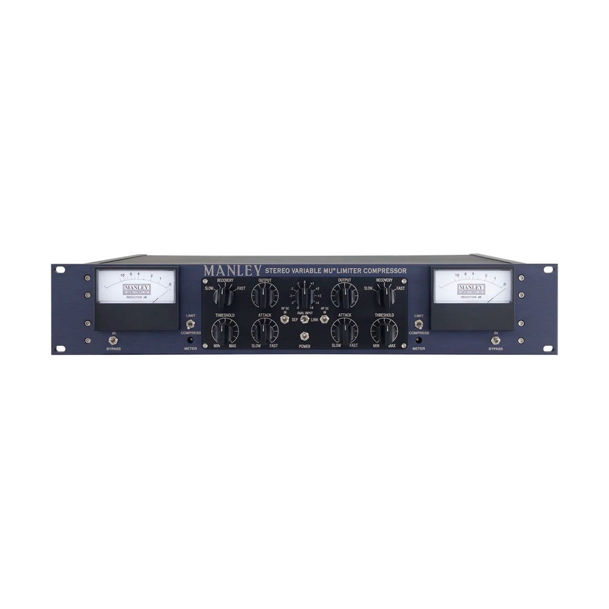
Manley Stereo Variable Mu MS T-Bar Mod is the valve compressor in its standard chassis fitted with both modifications: MS in the signal path and T-Bar in the gain control stage. The controls remain continuous, on conductive plastic potentiometers.
Fully equipped without stepped controls
Not every studio needs logable knob positions. If your work is mostly mixing rather than mastering, continuous controls are easier to fine tune by ear, and the modifications are what actually change the sound. T-Bar replaces two 5670 triodes with four 6BA6 pentodes and holds the smooth curve even at deeper reduction. MS splits the signal into centre and sides ahead of the gain stage, so you press on the middle without touching the space around it. Together they cover everything from gentle glue to heavy, creative processing.
The valve itself as the gain control
A variable mu circuit has neither a VCA nor an optical cell. Gain changes through the bias voltage of remote cutoff valves, so the reduction is not applied to the signal, it is how the amplifying stage behaves. That produces the characteristic response: the harder you push it, the gentler the curve looks, instead of a hard knee at the threshold. The mode switch gives 1.5:1 in Compress and 4:1 to 20:1 in Limit, attack is continuously variable from 25 to 70 ms, and recovery has five settings: 0.2 s, 0.4 s, 0.6 s, 4 s and 8 s. A high pass filter in the sidechain at -3 dB @ 100 Hz keeps the low end out of the detector so the kick does not drive the whole mix.
KEY FEATURES
- MS modification with mid-side encoding and decoding
- T-Bar modification: four 6BA6 pentodes in the gain stage
- Continuous control on conductive plastic potentiometers
- Two channel compressor and limiter with an all-valve path
- Compress mode at 1.5:1 and Limit mode from 4:1 to 20:1
- Attack continuously variable from 25 to 70 ms
- Recovery in five steps: 0.2 s, 0.4 s, 0.6 s, 4 s and 8 s
- High pass filter in the sidechain at -3 dB @ 100 Hz
- Manley IRON transformers with nickel laminations
- Channel linking for stereo operation
- Hardwire bypass for comparison against the unprocessed signal
- Illuminated Sifam gain reduction meters
TECHNICAL SPECIFICATIONS
- Variable gain valves: 6BA6 x4 in the T-Bar modification
- Amplifying valves: 5751 or 12AX7 x2
- Output valves: 12BH7 x2
- Sidechain rectifier: 12AL5 x2
- Frequency response: 20 Hz to 25 kHz (±0.1 dB)
- Maximum gain: 35 dB
- Maximum output: +30 dBu with 26 dB of headroom
- THD: below 0.1% at 1 kHz
- Noise floor: -85 dB typical
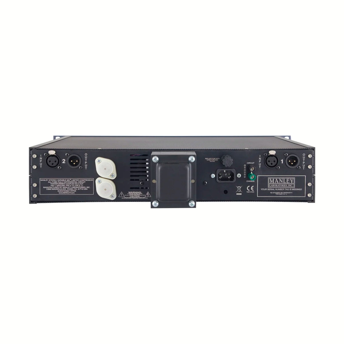
- Balanced inputs and outputs, 600 Ohm
- Controls: conductive plastic potentiometers, continuously variable
- Dimensions: 19 x 3.5 x 10 inches, 2U; power consumption 80 W